Required Components
About the CDS Cell
CdS (Cadmium Sulfide)A semiconductor that changes its resistance based on light intensity.
The resistance decreases in bright light and increases in darkness.
Photoelectric effect.
Resistance Divider Circuit
Since the CDS cell is a sensor whose resistance changes based on light intensity, the following circuit cannot be used.The reason is that the microcontroller can only measure voltage.

To avoid this, a circuit that converts resistance values to voltage values is needed.
The circuit used for this purpose is the resistance divider.
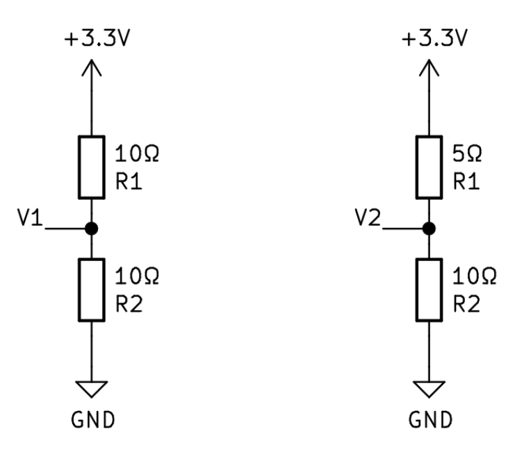
Assuming R1 is the CDS cell, when it gets brighter (the resistance of the CDS cell decreases)
V1 = R2 ÷ ( R1 + R2 ) × 3.3V = 10 ÷ ( 10 + 10 ) × 3.3 = 1.65V
V2 = R2 ÷ ( R1 + R2 ) × 3.3V = 10 ÷ ( 5 + 10 ) × 3.3 = 2.2V
As shown in the above formula, when the resistance of R1 decreases, the output voltage for the microcontroller increases.
Electronic Circuit
Circuit Diagram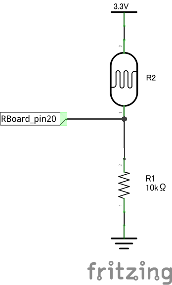
Breadboard Circuit Diagram

Program
Make LED1 light up when it gets dark
LED1 = 0
ADC1 = 7
adc = ADC.new()
adc.ch(ADC1)
while true
  adc.start
  v = adc.read_v
  adc.stop
  if(v < 1.7)
    digitalWrite(LED1, 1)
  else
    digitalWrite(LED1, 0)
  end
end