Required Components
- Breadboard
- Jumper Wire
- RGBLED(Common Cathode)
- Resistor(56Ω)
About RGBLED
-
It is an LED that combines red, green, and blue LEDs into one.
There are two types: Common Anode and Common Cathode, and we will use Common Cathode in this tutorial. Common Cathode is a component where the cathodes (-) of three LEDs are combined into one terminal.

It can express various colors from the three colors of RGB.
「Primary Colors of Light」

RGBLED Electronic Circuit
When checking the datasheet, the VF values of G and B are 3.6V, while the VF value of R is only 2V. When no resistor is used, the current values of G and B are 10mA, and R is 27mA. To set the current value to 10mA, according to Ohm's law:R = V / I = (3.3 - 2) / 0.01 = 130Ω
Although this results in 130Ω, in practice there is a range in VF values, and the datasheet also indicates that when IF is 20mA, VF is between 2~2.5V, so the resistor value can be around this range without any issues. Despite the various considerations, we will use 56Ω in this tutorial.
Circuit Diagram

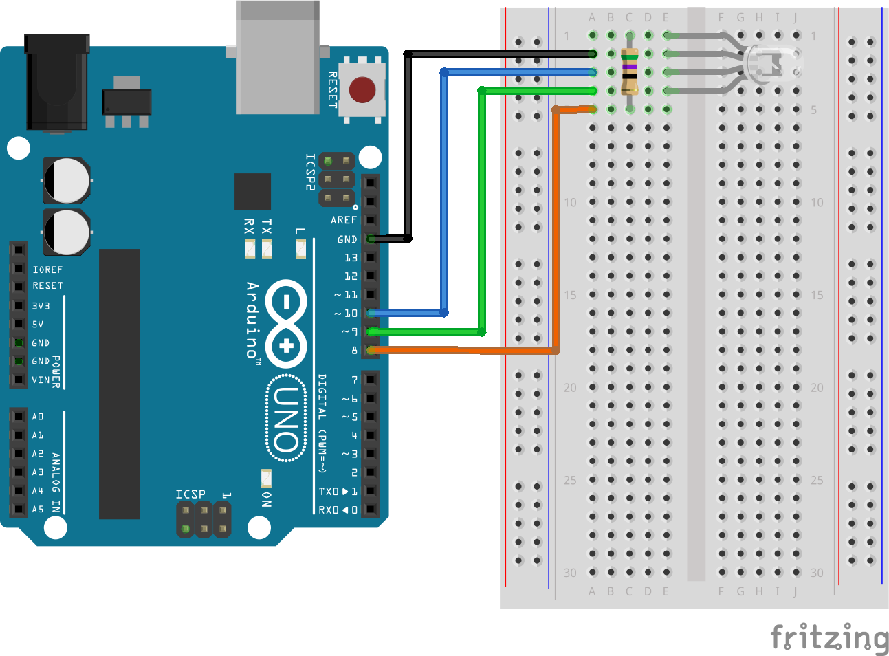
Breadboard Circuit
Program
A program that cycles through red⇒magenta⇒blue at 1-second intervals
LEDR = 15
LEDG = 16
LEDB = 17
pinMode(LEDR, 0)
pinMode(LEDG, 0)
pinMode(LEDB, 0)
while  true
  digitalWrite(LEDR, 1)
  sleep(1)
  digitalWrite(LEDB, 1)
  sleep(1)
  digitalWrite(LEDR, 0)
  sleep(1)
  digitalWrite(LEDB, 0)
end
Task:
- Light them up in the order of [green → yellow → red].
- Dim the LED brightness
- Dim the LED brightness (PWM)
LEDR = 15
LEDG = 16
LEDB = 17
pinMode(LEDR, 0)
pinMode(LEDG, 0)
pinMode(LEDB, 0)
while  true
  digitalWrite(LEDG, 1)
  sleep(1)
  digitalWrite(LEDR, 1)
  sleep(1)
  digitalWrite(LEDG, 0)
  sleep(1)
  digitalWrite(LEDR, 0)
end
LEDR = 15
LEDG = 16
LEDB = 17
pinMode(LEDR, 0)
pinMode(LEDG, 0)
pinMode(LEDB, 0)
while  true
  digitalWrite(LEDR, 1)
  sleep(0.001)
  digitalWrite(LEDR, 0)
  sleep(0.001)
end
LEDG = 16
pinMode(LEDG, 0)
PWM.new()
PWM.pin(LEDG)
PWM.start(2)
PWM.cycle(0x95A,4)
while true
  for i in 0..100 do
    PWM.rate(i,2)
    sleep(0.03)
  end
end